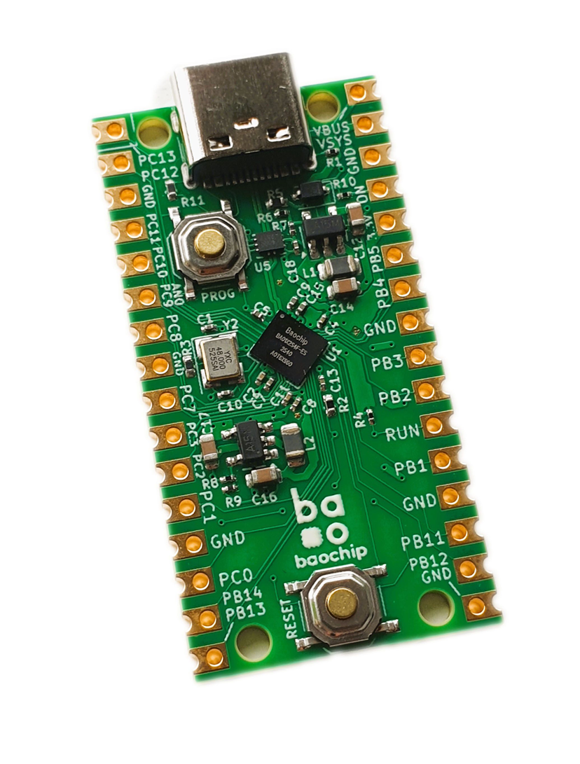
The Dabao boards are landing! and if you backed the Crowd Supply campaign or picked up a Baochip-1x some other way, you are now holding something about the size of a stick of gum with a USB-C connector, two buttons, and a mirror grey square in the middle. There are no LEDs on it, and nothing happens when you plug it in.
That is deliberate though, and this post gets you from that to a blinking LED without the two evenings it took me to work out the parts nobody writes down!
What you need besides the board
Soldering Iron, Solder and 2.54 mm headers. The Dabao ships with castellated edges, so the first thing I recommend you do is solder on some 2.54mm headers.
A USB-C data cable. The cable has to be a proper USB-C cable, not a charge only cable. This is the single most common way people lose an hour on day one, because the board powers up perfectly and never enumerates, so it looks like a dead board rather than a dead cable. If you have a drawer of anonymous USB-C cables, test with one you know carries data.
A USB to serial adapter. I recommend the CP2102 or CP2104. That rule isn;t hard and fast though as a CH340 or FT232 based one will work fine, any of which cost a couple of dollars. for safety make sure it goes up to 1 MBaud, though most of the time you'll be using it at 115200 baud, so most modern USB to serial adapters will work. This is not optional if you want to see anything your own program prints as the Dabao's USB port talks to the bootloader, not to your code, so your program's output has to leave the board on a separate UART.
Make sure it is a 3.3V adapter. Some older FTDI cables output 5V and will kill the chip.
A breadboard, an LED, a resistor, and two jumper wires. The board has no onboard LED. bunnie left it off to keep the thing small and cheap, so your first blink is an external LED. A 330 ohm resistor gives you roughly 5 to 6 mA, which is comfortable. 1K gives you about 1.3 mA and a dimmer LED, which is also fine, but at minimum you'll need this to run some of your programs.
No debugger. There is no ICSP header, no onboard debug probe, and nowhere to attach an external one. Debug access is fused off at the factory and boot1 checks that it stayed off on every boot. For a chip whose whole purpose is being trustworthy, an open debug port would undo the work so everything happens over USB and serial instead. I think of it as a plus since you can just plug in the board and go without much hassle.
The 3.3V rule, before anything else
The Baochip-1x is a 3.3V part and it is not 5V tolerant. Maximum on any I/O pin is 3.63V. Unlike some microcontrollers that quietly clamp an overvoltage through their protection diodes, this chip has no such safety net, you apply 5V to a pin and you risck damaging your board. Coming from a Pico, an ESP32, an STM32, or a Raspberry Pi, you are already at 3.3V and can wire directly. If you're coming from an Arduino Uno, you need a level shifter or a divider on anything originating at 5V.
Software
If you're going the C route then there are two pieces of software you need to get.
The xpack RISC-V toolchain, version 15.2.0-1 or later, from the xpack releases page:
https://github.com/xpack-dev-tools/riscv-none-elf-gcc-xpack/releases
Use the xpack build specifically. Distribution packages and Homebrew formulas produce toolchains with different target triples, usually riscv64-unknown-elf or riscv32-unknown-elf, which means different binary names and different default flags. The build script will not find them. If you already have a RISC-V toolchain installed for other work, leave it where it is and install the xpack one alongside.
Extract it into the SDK root so the layout looks like this:
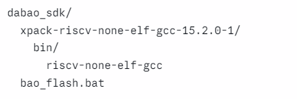
The build script finds it from there. Adding the bin/ folder to your PATH works too.
Python 3 and two packages:
pip install pyserial pure25519
pure25519 does the Ed25519ph signing. More on why that matters in a moment.
Then clone the SDK:
git clone https://github.com/ArmstrongSubero/dabao-sdk
Wire the serial console first
Do this before you write any code. Three wires, and the data lines cross over.
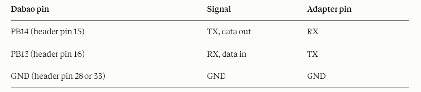
TX to RX, RX to TX. Wiring TX to TX is the most common mistake in all of embedded development and the symptom is simply nothing on the terminal, which tells you nothing about the cause.
Open a terminal on the adapter's port at 115200 baud, 8N1, one thing worth filing away now, PB13 and PB14 are the default serial console, and boot1 configures UART2 on them at startup. If you later repurpose those pins, you lose the bootloader's serial shell along with them.
Wire the LED
PB1 is header pin 29 on the right hand header. Jumper from PB1 to one leg of the resistor, other leg of the resistor to the anode of the LED, which is the long leg. Cathode, the short leg, to any GND pin.
It makes no electrical difference whether the resistor sits before or after the LED, since it is a series circuit and the same current flows through both.
Prove the chain works before writing anything
The SDK ships with a blink example. Run it first. The point is not the LED, it is proving that your toolchain, your signing setup, and your flashing path all work, so that when something breaks later you know it is your code and not your environment.
Windows:
bao_flash build blink
bao_flash flash COM9 blink
Linux and macOS:
chmod +x bao_flash.sh
./bao_flash.sh build blink
./bao_flash.sh flash /dev/ttyACM0 blink
COM9 and /dev/ttyACM0 are examples. You now have two serial devices attached, the Dabao itself and your USB to serial adapter, so check which is which before you start guessing.
bao_flash list shows the available examples. bao_flash run <port> <example> builds and flashes in one step.
If the LED blinks, everything from your text editor to the silicon is working.
Bootwait, and why you are not holding buttons
This is the part that confuses people arriving from other boards, and it is good news.
The Dabao ships with bootwait enabled. It comes up in the boot1 REPL ready to be programmed rather than running application code. You do not hold any button for a first flash.
Better still, bootwait stays enabled after flashing. Press RESET and you are back in the boot1 REPL, ready to flash again, without touching a button. That is the mode you want for the whole time you are developing.
When you want firmware to run automatically on every reset and power cycle instead, add --persistent:
bao_flash run <port> <example> --persistent
What The Two Buttons Do
RESET is wired directly to the RUN pin. It restarts the chip.
PROG activates the USB mux on the board, which physically disconnects and reconnects the USB data lines. boot1 sees that and enumerates the chip as a USB mass storage device and a serial port at the same time. A drive appears on your computer and you flash by copying a .uf2 file to it.
To get back to the boot1 shell from a running program: hold PROG, press and release RESET while still holding PROG, wait about a second, then release PROG.
Worth knowing where the floor is: that mass storage drive is served by boot1, not by anything in silicon. It works no matter what state your own firmware is in, because your code never runs before boot1 has already enumerated. It is a genuine recovery path.
Some Troubleshooting Tips
Nothing enumerates at all. Cable. Try another one that you know carries data.
No mass storage drive when you press PROG. Same answer. Cable.
LED does not light. Check the LED is not in backwards. Anode is the long leg and goes toward the resistor.
Nothing on the serial terminal. TX and RX are almost certainly straight through instead of crossed.
Code flashed but does not seem to run. Type audit in the boot1 REPL. The "Next stage" line tells you exactly what the bootloader made of your image. If it shows key 3/3 (dev) -> 60060000 then the boot chain is working correctly and the problem is in your code, so look at your crt0.S, your linker script, or main().
Nothing on audit and the port is unresponsive. Unplug, wait a few seconds, plug back in. boot1 occasionally needs a full power cycle to recover from a crashed USB stack.
Some Things You Need To Know
Now that the LED is blinking, here is what is waiting for you, so you recognise it rather than losing an evening to it.
Your DMA buffers must be in IFRAM, not SRAM. Every serial peripheral on this chip goes through a subsystem called UDMA. There is no transmit data register you write a byte to. You put the byte in a buffer, hand the UDMA the address, the size, and a start, and it does the transfer. The catch is that the UDMA's address decoder does not reach SRAM at all. Put your buffer in SRAM and the transfer fails silently. No error, no crash, just nothing. IFRAM lives at 0x50000000. This is the single most important hardware detail on the chip.
Ed25519ph is not Ed25519. Every bootable image carries a 768 byte signature block, and the signature is Ed25519 prehashed, per RFC 8032, with a domain separator. Standard Ed25519 tooling will produce something the chip rejects, so PyNaCl and OpenSSL's Ed25519 mode will not do it. The sign_and_uf2.py in the SDK handles it correctly.
The developer key erases the device secrets, permanently. Bare metal images are signed with the developer key in slot 3, whose private key is published deliberately. When boot1 validates a developer signed image it boots normally and wipes the hardware key store and the derived key material. That is a deliberate anti tampering mechanism, and once it happens the device is permanently marked as a development unit. For blinking LEDs, reading sensors, and everything else in ordinary embedded work, this costs you nothing at all. Worth knowing before it happens rather than after.
Clock changes need a commit. You write divider values to their registers and nothing at all happens until you write 0x32 to SFR_CGUSET. Forgetting the commit write is a standard first mistake with the clock tree.
Where to go from here
You have a board that boots, a toolchain that builds, and a flashing loop that does not require holding buttons. That is the hard part of any new chip and it is behind you.
Next up is UART, because a blinking LED proves your code runs but you cannot debug anything without seeing what it is doing. That is where UDMA and the IFRAM rule stop being trivia and start being the thing standing between you and a working printf.
The dabao-sdk covers all of the peripherals with drivers and examples under Apache 2.0, so if you want to get moving rather than read registers, start there.
For background on why the chip exists at all, bunnie's 39C3 talk on Xous and the Baochip-1x is the place to go 39C3 - Xous: A Pure-Rust Rethink of the Embedded Operating System, and the Baochip Discord is where people actually ask questions. bunnie answers in it directly, which is not something you can say about most silicon. you might also find the datasheet link helpful Introduction - Coder's guide to the Baochip 1x
If you want the register level detail underneath it, including the undocumented behaviour and the places where the silicon disagrees with the SDK, that is The Dabao Book is your resource where I tested a lot of stuff in C and will save you a lot of time.
Corrections are welcome and get credited in the next edition. This chip is new enough that I would rather know.